
Wigglegrams!
Amateur Gemstone Faceting contains a number of 3-dimensional diagrams that literally “pop” out of the page. Unfortunately, a significant fraction of readers will have difficulty merging the images and seeing the effect. For more, refer to Chapter 11.9.2 and page 74 of Volume 2.
Wigglegrams represent a viable alternative for those who cannot use the 3D diagrams in the book. It turns out that the human brain can synthesize a three-dimensional image when presented with rapidly alternating left eye – right eye views of a scene.
The gallery below presents almost 30 wigglegrams of all the 3D images in Amateur Gemstone Faceting. Enjoy!
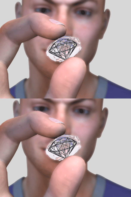
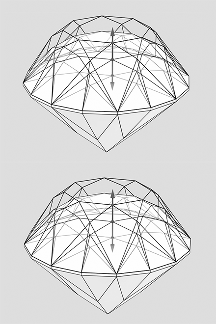
Figure 6-21 Examine your gem rough from all angles, and try to project the gem design inside the stone.
Figure 10-15 Scaling the crown using the tangent ratio. Each vertex moves up or down (see arrows), but does not shift along the other two dimensions.
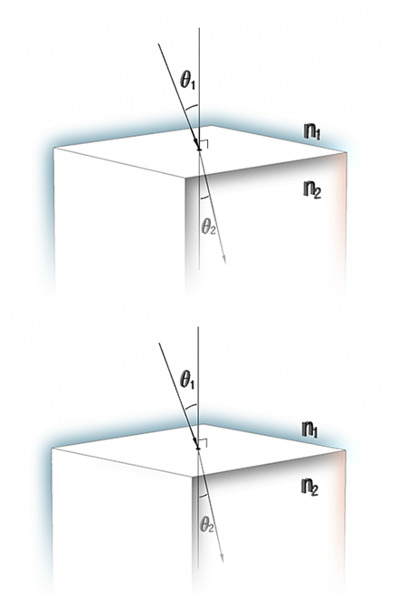
Figure 11-9 The angle of incidence and refraction for two media of refractive index n1 and n2. Note that the angles are measured with respect to the perpendicular to the surface. Yes, this is the same drawing as Figure 10-7. To make it up to you, this one is in 3D! (and this version a wigglegram). Section 11.9 explains 3D imagery and can help if you have difficulty.
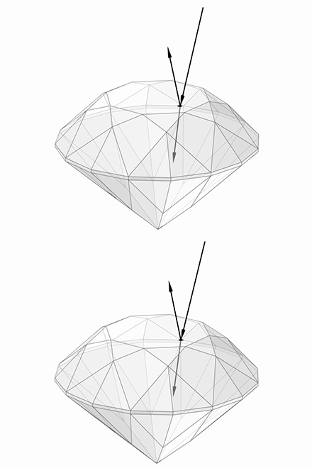
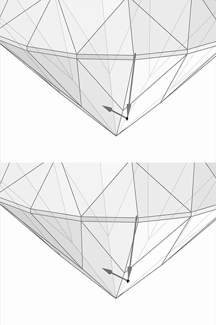
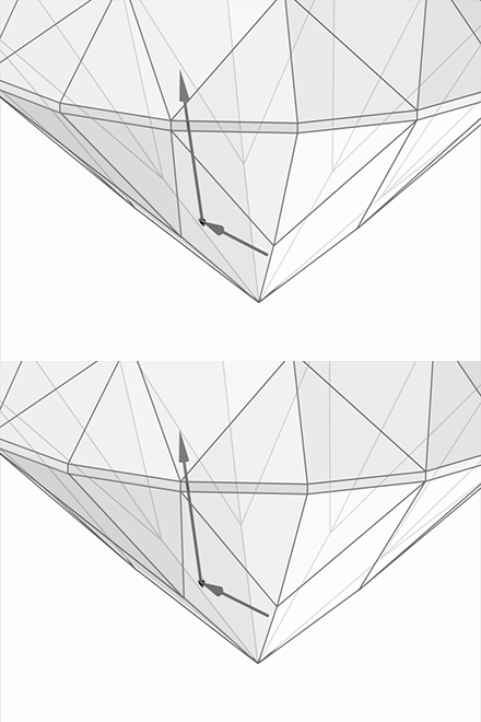
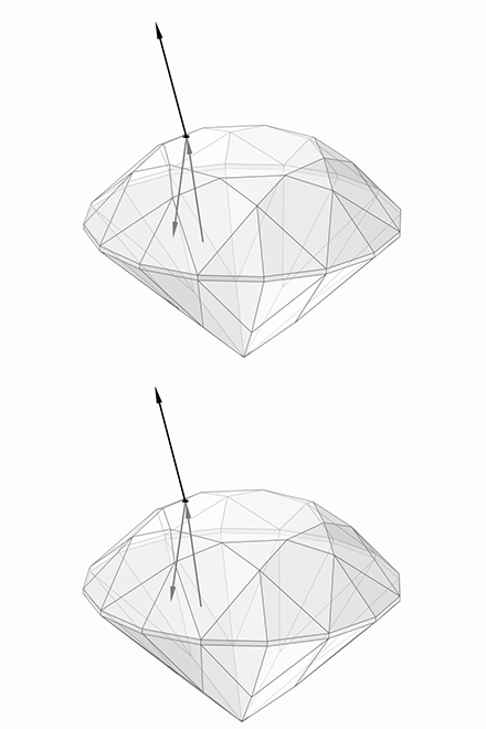
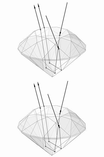
Figure 11-21 Light strikes the table of an SRB. Fresnel loss causes a fraction of the rays to reflect off the surface, while the remainder enters the gem. Some reflected rays will have the appropriate direction to be seen. Click the arrows to follow the light.
Figure 11-22 The rays continue into the stone and strike a pavilion facet, where total internal reflection sends them back into the gem. Click the arrows for more.
Figure 11-23 The rays cross the pavilion and strike another main facet, again above the critical angle. The totally reflected rays then head upward. Click the arrows for more.
Figure 11-24 At the edge of the table facet, most rays are refracted and escape the gem. Fresnel loss again causes a 7% reflection, and those rays head back into the stone. Click the arrows for more.
Figure 11-25 Two rays approaching from radically different directions in the environment emerge next to each other and parallel. To the observer, the stone slices up the scene and scrambles it, producing rich scintillation.
<
>
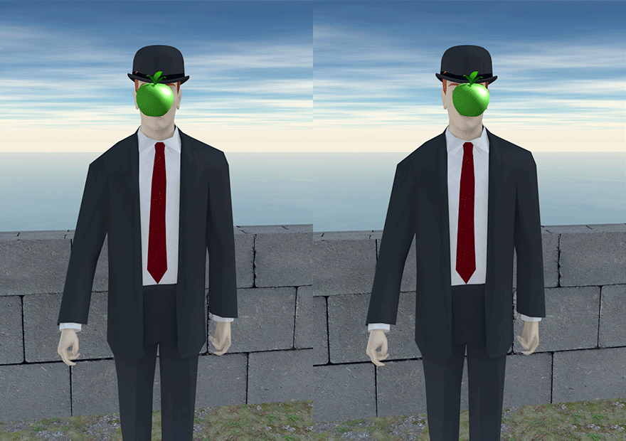
Figure 11-27 My wigglegram version of René Magritte's 1964 masterpiece, The Son of Man. The brain can extract three-dimensional information from a scene by correctly overlapping the right-eye and left-eye views. Chapter 11.9 explains how our brains and eyes work together to help us appreciate the world around us, especially gemstones!
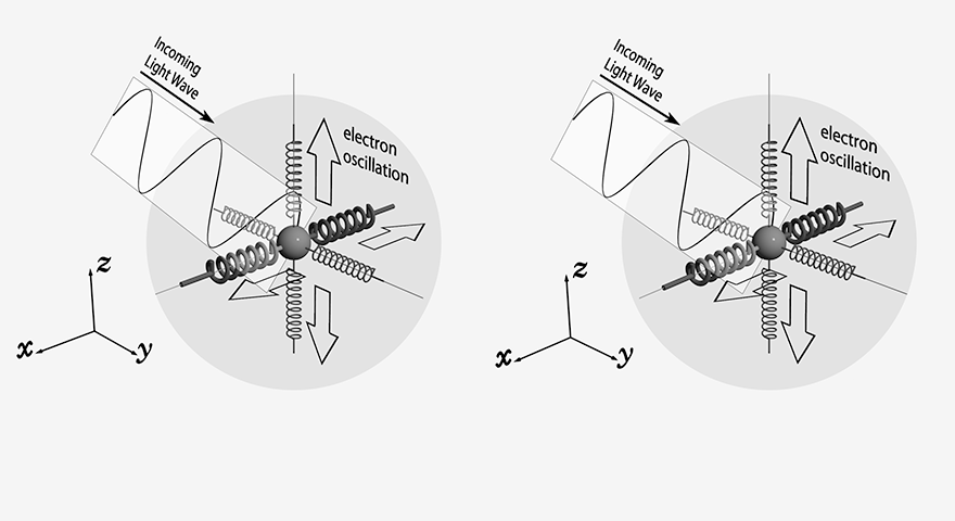
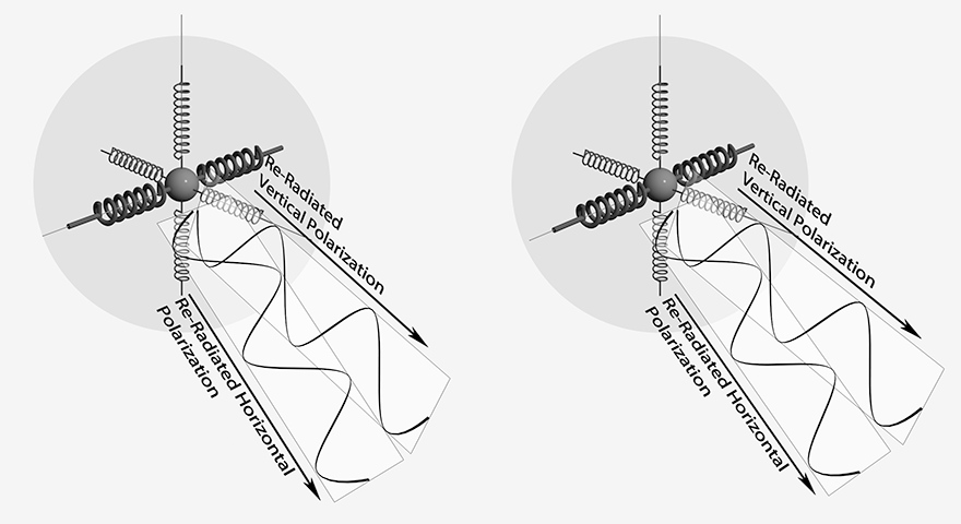
Figure 12-10 A light ray interacting with an atom in a birefringent gemstone. This phenomenon arises in anisotropic materials when the “spring strength” is different along different crystal directions.
Click the arrows to see the light ray emerging from the atom.
Figure 12-11 After interacting with the electrons, the emerging light wave splits into two distinct polarized waves that take two different paths through the crystal. Differences in the absorption properties for the two polarizations can lead to colour differences in different directions, the phenomenon known as pleochroism.
<
>
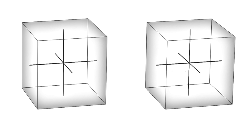
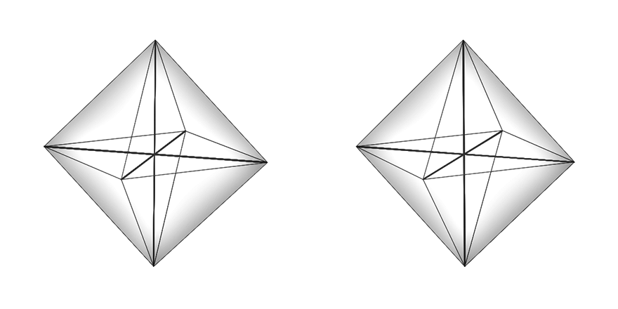
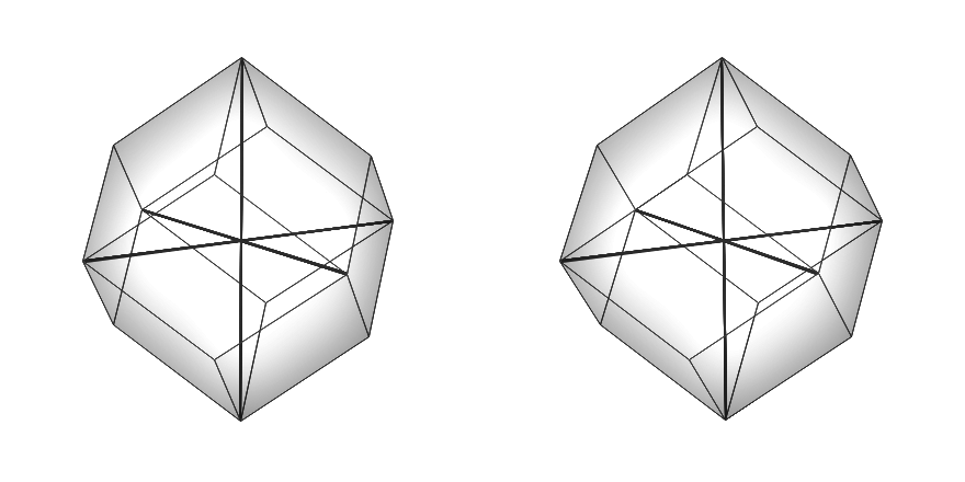
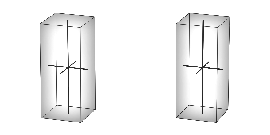
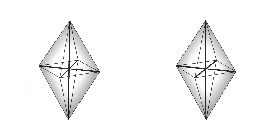
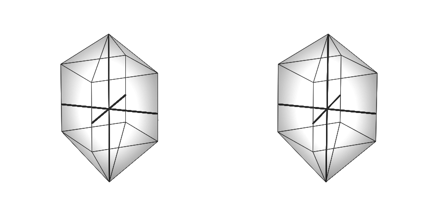
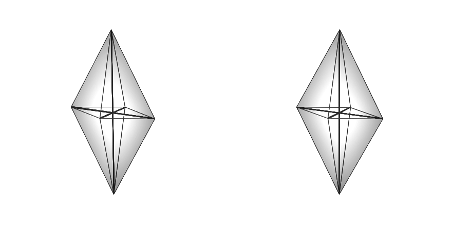
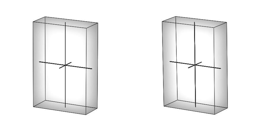
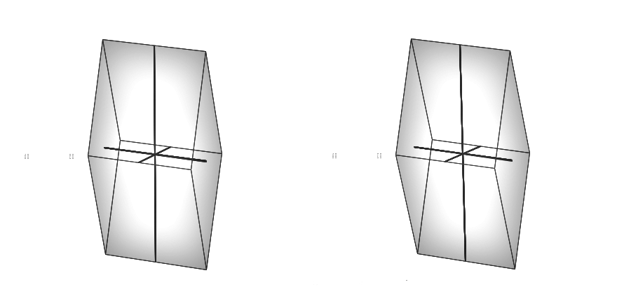
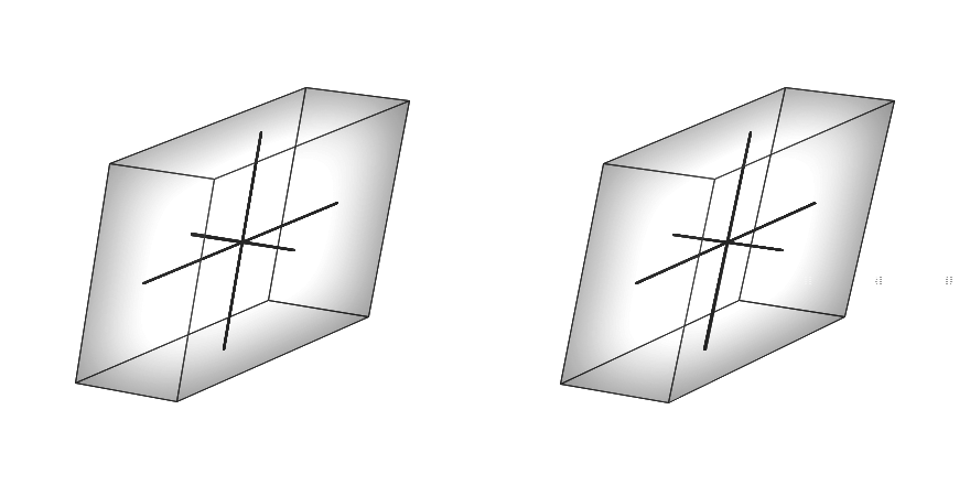
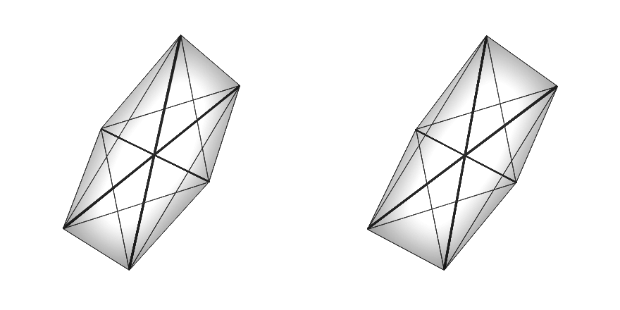
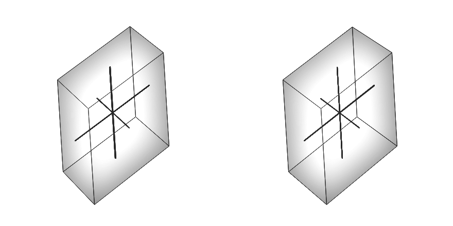
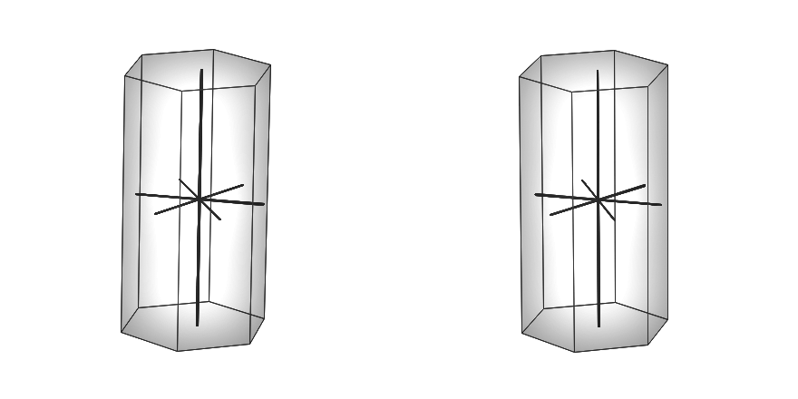
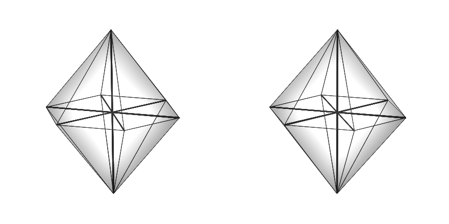
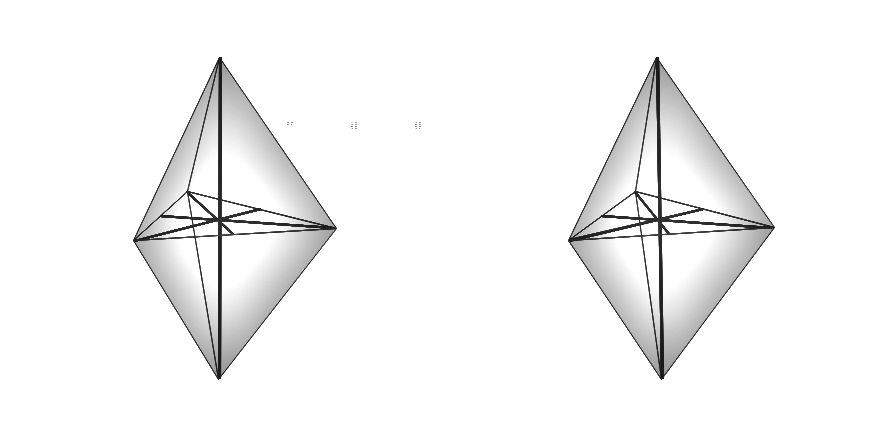
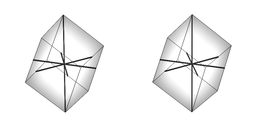
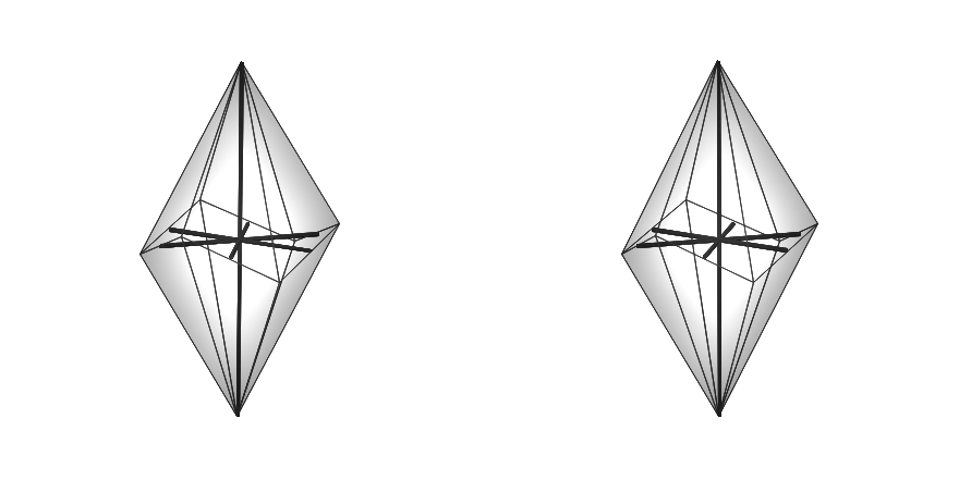


Figure 12-34 The cubic form of the cubic or isometric crystal system. Examples: fluorite, iron pyrite.
Figure 12-34 The octahedral form of the cubic or isometric crystal system. Examples: diamond, spinel.
Figure 12-34 The dodecahedral form of the cubic or isometric crystal system. Example: garnet.
Figure 12-35 The rectangular prism form of the tetragonal crystal system.
Figure 12-35 The dipyramid form of the tetragonal crystal system.
Figure 12-35 The mixed rectangular prism - dipyramid form of the tetragonal crystal system.
Figure 12-36 The dipyramid form of the orthorhombic crystal system.
Figure 12-36 The rectangular prism form of the orthorhombic crystal system.
Figure 12-36 The kite-shaped prism form of the orthorhombic crystal system.
Figure 12-37 The monoclinic crystal system.
Figure 12-38 The dipyramid form of the triclinic crystal system.
Figure 12-38 The inclined asymmetric prism form of the triclinic crystal system.
Figure 12-39 The prism form of the hexagonal crystal system.
Figure 12-39 The dipyramid form of the hexagonal crystal system.
Figure 12-39 The three-sided dipyramid form of the trigonal crystal system.
Figure 12-39 The rhombohedral form of the trigonal crystal system.
Figure 12-39 The scalenohedron form of the trigonal crystal system.
<
>
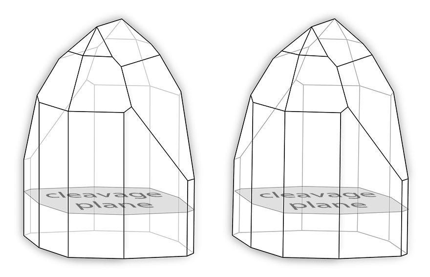
Figure 12-40 Typical crystal form of topaz and the dominant basal cleavage plane. See Chapter 12.11.1 for more.
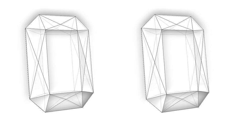
Figure 16-22 A tablet-type design can highlight the colour of saturated gem material. Yes, this is another one of those annoying 3D drawings. See Chapter 19.2.3 for a real-world design.
Site Manager: Tom Herbst
Last Updated:
26 October 2014